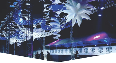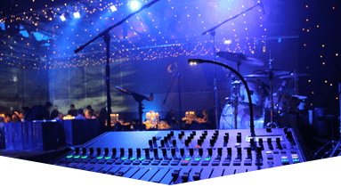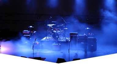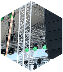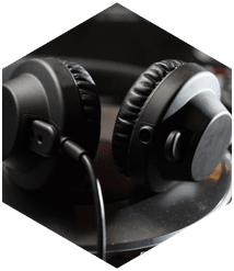
For Sound and Lighting in Miami that is sure to take your next event to new heights, call the trusted professionals at Master Sound Productions. Our lighting and sound equipment comes in a variety of options, which we are sure will leave your guests speechless. If you are looking to enhance the sound of your next event or production, we offer speaker rentals, outdoor sound system rentals, power amp rentals, live sound rentals, FOH mixing consoles, mixer rentals, microphone rentals, DJ gear rentals, pioneer mixers, and so much more. If you are looking to create a magical atmosphere with lighting, we offer dimming and controller rentals, LED lighting rentals, intelligent lighting rentals, follow spots lighting rentals, and so much more.
Here at Master Sound Productions, we can surely provide you with high-quality rentals and dependable services for any event that you are planning to host. Since 1996, we have been in business, and we have built a stellar reputation throughout South Florida and beyond. We are frequently praised by our customers for our professional staff and affordable prices. We will be happy to deliver your Sound and Lighting in Miami or any other rental and set it up for you. We are best known for our exceptional rental equipment, which includes sound, lighting, staging, dance floors, DJ services, tables and chairs, tents, backline, fabric, and so much more.
Master Sound Productions provides a strong base to build long-term relationships with our clients. Call us for unrivaled Rental, Production & Event Labor services in Miami, Broward, Palm Beach & Florida Keys. We have the lowest rates on Sound Equipment Rentals, Lighting Rentals and Portable Stage & Truss Rentals. We stock only the top brands. Our team is certified in Sound Engineering, Monitor Engineering, Lighting Designs, Riggers & Stage Hands.
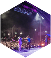
Our goal is not to be the biggest event production source in South Florida but to be the very best one. Our passion, experience, and boundless creativity, will help ensure that we offer the best production company in Miami, Broward, Palm Beach and the Florida Keys. Since our initiation, every carefully-selected member of our Team has been hired because of sharing the same passion, and desire, to be remarkable. Let us help you with your next special event.